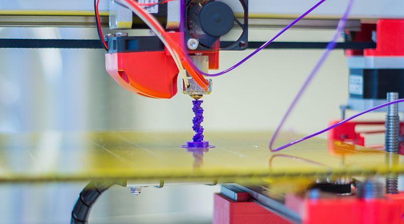
Welcome to part 4 of the 3D printers series of posts. In part 1 we covered the basics of 3D printing as a STEAM project, and in part 2 we covered the building of a 3D printer, the electronics and keeping safe in an education environment. Part 3 was dedicated to the engineering, mathematics and art components of the enclosure and the scientific components of the 3D printing filament. In this part, we will cover the technology, art, mathematics, and engineering within the design of 3D objects using software, as well as the technology and mathematics within the programming of the 3D printing firmware.
Designing the Model
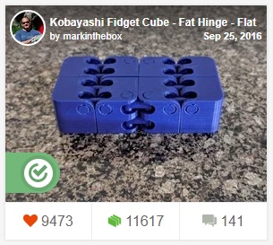
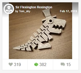
For many, designing and creating the 3D model is the very first stage of the 3D creation process. Fortunately, for those that are not able to do that due to lack of software or know-how, there are websites like Thingiverse and Cults3D where you can search for and download 3D models for free or for a fee. This is a great resource for getting ideas, not just to print but to adapt, which is how I started. My favourite designs are the Kobayashi fidget Cube, the simple whistle, and Sir Flexington Rexington.
 |
 |
 |
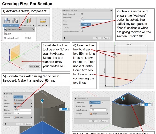
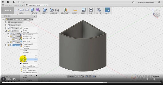
After finding and downloading many ready-made models, I found that the designs I wanted to update my printer were not available, so I had to create them myself by adapting designs. This is when I decided to create them myself. To do this I used Autodesk Fusion 360, which is 3D design software that is free for teachers and enthusiasts. To be honest, I didn't find Fusion 360, or any other 3D design software (I tried Blender and Sketchup) very intuitive. It took me a good while to get my head around the software and find my way around it. However, when I did manage to figure out how things worked, it was ok. One great resource I used was Fusion 360 Tutorials from Warwick University.
These tutorials are in video and written format which is great for differentiation.
 |
 |
This part of 3D printing is very much about learning how to use the software package and not just general knowledge, which is why the tutorials helped so much. The first thing I had to do was learn how to navigate the software and show different views of objects on the screen. For example, pressing the mouse scroll wheel and moving the mouse allows you to pan around the plane in view, holding shift while doing the same allows you to rotate the view around spherically in the 3D space. As can be expected, scrolling in and out with the mouse wheel zooms in and out. Common tools I used, which linked quite nicely with engineering techniques were:
- Rectangle and circle sketching which created single plane shapes, which could be used for other things.
- Extruding, which made the 2D sketches into 3D shapes. This also created holes, if you extruded a shape into another shape.
- Resizing, splitting and combining shapes were found within the modify section and were used to further manipulate new and existing shapes
- Inserting Mesh objects allowed me to insert existing STL files which I downloaded from Thingiverse or other online repositories.
The mathematics components can come in many forms. Like many other 3D design software, the number of polygons used to create an object determined many other characteristics of that object. You could liken the polygon count to its 3D resolution. The higher it is, the higher the quality of the object, but also the larger the file, and the longer it takes to process, meaning it would be more difficult to manipulate. In some cases, in order to change an object the way I wanted, I had to reduce the polygon count of the object, which had the risk of reducing the quality. In most cases, this was not an issue. However, If I was working with a lithophane of a photo image of a person (240,000 polygons for one of mine), then the quality of the end product would be greatly affected as each polygon represents ridges and dimples or features on a persons face and body.
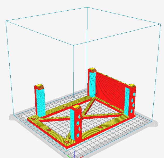
As everything is in dimension with the software, scaling and measuring can be done with high levels of precision, fractions of a millimeter (or inch, depending on preference) if needed. This comes in extremely useful when creating an object to fit part of the 3D printer. One of the objects I downloaded from Thingiverse for my printer, a power supply bracket, was made to different dimensions to what I needed. After importing it into Fusion 360 I was able to manipulate the image to change it from its original dimensions (120 x 210 x 60 mm) to desired measurements (131.5 x 178.5 x 72.3 mm) by using the tools mentioned above.
In a classroom setting, using Fusion 360 or any other 3D design software would be great for teaching how to create or adapt an object using mathematics for scaling resizing and reshaping and many other things. It also shows a different perspective of the final printed object. Students can really show artistic flair here, as well as the mathematics and engineering skills. Once the final object is saved as an STL it can be used within the slicer and turned into GCode. This leads quite nicely to the next section about programming.
Programming - Technology and mathematics
Before I go into the GCode, I want to talk about the core programming language for Arduinos. Mainly because 3D printers that run off 8bit processors most likely work with Arduino technology and run using firmware called Marlin. This manages the commands that are sent to the 3D printer to print your object. Arduino microcontrollers are essentially small computers that have the ability to control things -like 3D printers. Depending on which 3D printer you have, Marlin may already be installed. For the Anet A6 and many other lower priced kit printers, Marlin probably won't come pre-installed. However, it would be a good idea to install it, due to Marlin's features, some of which are geared towards safety. Once it is installed, if you decide to do so, the only involvement with the code you would have would be to change settings or add/remove features using the configuration.h file. So not much involvement with programming at all. However, now would be a good time to introduce Arduino technology and C/C++ programming to the students.
The real programming with 3D printers comes with GCode (Geometric Code), which is the language used to give instructions to the printer to control geometric movements within a 3D space and machine settings. Again, it is quite possible to use 3D printers without knowing any GCode at all. A little knowledge of it does help but knowing more really highlights the programming and control aspects of 3D printing. It's a numerical control programming language, so unlike languages like Python or Java, it doesn't have variables, loops or conditionals. It just describes the movements required to create the 3D model. The GCode used to print a model is created by software called a Slicer. The slicer takes the 3D image created by 3D design software like fusion 360 for example, and separates, or slices the design into horizontal layers. It then decides which 3D printer movements are required to produce each slice of the model and then converts those movements into code. An example of GCode is below.
G1 X-9.2 Y-5.42 Z0.5 F3000.0 E0.0377
G1: This is the command for 'Controlled motion', which means the print head will move at a specified speed (or feed rate) to a specified location, with the ability to extrude a certain length of filament. This is in contrast to a G0 'Rapid motion' movement, which will travel at the fastest printer speed to a specified point without the ability to extrude any filament.
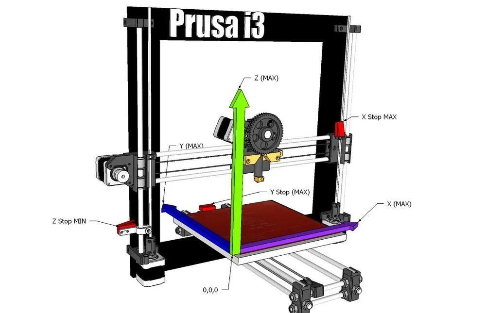
X-9.2 Y -5.42 Z0.5: This is the end location of the movement, specified in 3D coordinates. 3D printers can use both absolute and relative coordinates but usually uses absolute coordinates. The X0 Y0 Z0 location is usually at the bottom left corner of the square (or rectangular) 3D printing bed. Check out this article on '3D Printer Axis – All You Need To Know' by Brian Obudho to learn a little about 3D printer axis and learn about the difference between the standard Cartesian coordinates used below, and the Delta printer coordinates.
F3000.0: This is the command for the Feed Rate or speed of the movement measured in mm/minute.
E0.0377: This command tells the printer to extrude 0.0377mm of filament while the print head is moving.
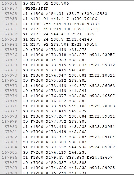
This sums up that line of code but the GCode file for a 3D object, created by a slicer, is made up of many many lines like this. The image below of a power supply bracket was exactly 168,044 lines long, nearly 5MB in size.
 |
 |
Although there is no scope for looping or conditionals, it is still a really good learning process, as you can play with many other types of commands, like changing the units from mm to inches (G20); absolute (G90) or relative (G91) mode, which we discussed above; clockwise motion (G2), or anticlockwise motion (G3); and setting commands like to start heating the extruder (M104) or the heating bed (M140); and to not carry on any other commands until the temperatures are reached in the extruder (M109) and the heating bed (M190); and to set the fan speed (M106). There are many other types of commands. For more explanations, check out these great articles '2019 3D Printer G-Code Commands: Programming Tutorial' by Dibya Chakravorty for All3DP, the 3D Printing G-code Tutorial from Simplify3D, and the Wikipedia page for GCode.
This pretty much sums up part 4 of this series, which covered 3D design software which used art, mathematics, and engineering, and also covered programming, which used technology and mathematics STEAM components. The next part will be the last part which will cover other software that can be used, namely the slicer, which represents, science, technology, engineering and mathematics components. We will also cover possible networking options that are available and extend the use of the 3D technology which represents the technology STEAM component.
Sources